Fast and Reliable Recognition
January 20th, 2020
Overview of Fast and Reliable Recognition of parts
by Ivar Balslev, Senior developer, Scape Technologies
Content
- Introduction
- 3D scanners of Scape Technologies
- Challenges with parts having a single plane surface facing upwards
- Flat, thin sheet metal part: Challenges with emptying the bin
- Supplementary classification during orientation control
- Shiny parts
1. Introduction
Among the bottlenecks of bin-picking is establishing reliable recognition of the randomly piled parts in the bin. By ‘recognition’ we sometimes mean classification and pose estimation of objects, sometimes pose estimation only. In fact, the name SCAPE is an acronym for Smart Classifier And Pose Estimator. However, most SCAPE cells handle only one type of parts, and so the presence of other part types than trained occurs very rarely. In other words, the recognition is normally limited to pose estimation.
The most generic recognition method is 3D scanning. SCAPE Technologies uses three methods in 3D scanning as described in Sec. 2. Non-shiny parts with non-planar surfaces are well suited for this recognition method. The same is true for non-shiny parts with more than one plane surface region facing the scanner.
In this document, we first describe the 3D scanners supplied by Scape Technologies (Sec. 2). Then we list a few cases (Sec. 3-6) where SCAPE Technologies has encountered performance problems. They have needed or will need cumbersome development.
2. 3D scanners of Scape Technologies
The following 3 scanner types are supplied by Scape Technologies:
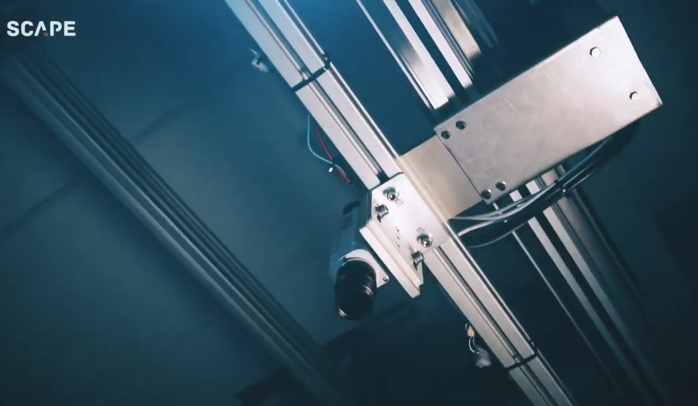
- SCAPE Sliding Scanner, see Fig. 1. Here a pair of lasers emit light along inclined planes. The laser pair and a camera viewing vertically down are mounted on a sliding system (item 2 in Fig. 1). The resulting point cloud contains up to 2.000.000 points. This scanner has the advantage that 2 - 5 bins (each with width 1200 mm) in a row can be scanned by the same scanner because the sliding rail can be made very long. Another advantage of the sliding scanner is the large range. The scanner camera can be mounted up to 1.8 m above the bin top, and so, rather large robots can be used.
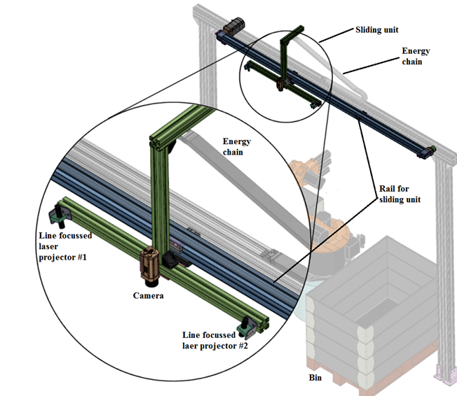 Fig. 1 – Structure of SCAPE Sliding Scanner. The sliding unit with lasers and camera is shown green. The two-line focused laser projectors are alternatingly active.
- SCAPE Stationary Scanner, see Fig. 2. Here a light projector emits sequentially up to 10 different patterns onto the scene, and a camera acquires an image of each pattern. The resulting point cloud contains up to 2.000.000 3D points. This scanner can handle a bin of horizontal size 1000mmx1300mm and depth of 800mm.
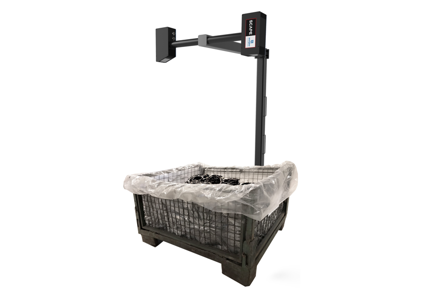 Fig. 2 - SCAPE Stationary Scanner.
- SCAPE Grid Scanner, see Fig. 3. This sensor is robot mounted. Here a LED projector with a stationary mask inside the lens emits light onto the scene and a camera acquires two images per scan, one with the projector on, one with the projector off. The resulting point cloud contains up to 32.000 points. The field of view can be set to 224mm x 224mm to 395mm x 395mm depending on the object scanner distance.
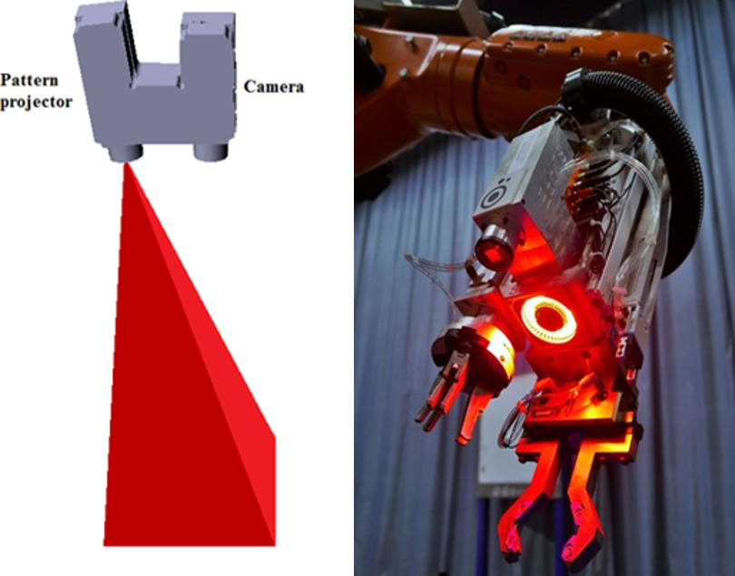 Fig. 3 – Left: Diagram showing the SCAPE Grid Scanner (top) and its projected rays. Right: The grid scanner mounted on a tool unit which also has a ring light and two-finger grippers.
Common to these scanning methods is ‘triangulation’: The 3D position of points on the scanned surface is calculated from the knowledge of the ray direction from the point to the projector and the ray direction from the point to the camera. The primary output is a ‘point cloud’, i.e. a list of 3D points, corresponding to surface points which are visible to both the camera and the light source (laser or LED projector). The point cloud from the scanner is fitted to the part shape defined by a CAD model. This fitting process is complex since the point cloud contains mixed information from several parts in the scene.
The scanners require that the scene is not too illuminated by ambient light. The SCAPE Sliding Scanner and Grid Scanner both use red light, whereas the SCAPE Stationary Scanner uses blue light, so the shielding against ambient light should block the red and blue spectral components respectively.
3. Challenges with parts having a single plane surface facing upwards
With a limited spatial resolution such as that of the SCAPE Grid Scanner, the pose estimation of parts with only one planar surface facing the scanner is often uncertain. SCAPE Bin-Picking solutions using a SCAPE Grid Scanner sometimes operate with so-called sensor fusion. Here the poses derived from the point cloud from the 3D scanner are compared with the contours derived from a 2D image of the same scene. The scanner-derived poses which do not contain the correct 2D contours are filtered out. An example is shown in Fig. 4.
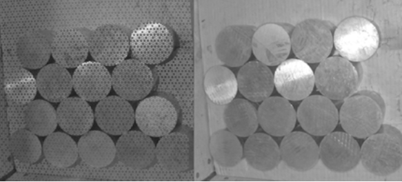
Fig. 4 – Left: Image used for the 3D scanning. Right: a 2D image of the scene illumined by a ring light, acquired by the same camera as used by the SCAPE Grid Scanner.
4. Flat, thin sheet metal part: Challenges with emptying the bin
When a bin is almost empty, the bin bottom point cloud should not be misinterpreted as belonging to parts. This sometimes becomes difficult when the parts are thin and flat, such as in the case of non-machined sheet metal parts. The distinction between parts and bin bottom becomes particularly difficult if the bin bottom is not planar and has an uncertain position in the global frame. Scape Technologies has developed sophisticated algorithms enabling the distinction between bin bottom and part.
5. Supplementary classification during orientation control
There is always a risk that a ‘wrong´ part is lying in the bin. ‘Wrong’ means that a part has a size and shape different from that of the ordinary part. Such wrong parts should never be fed into automated processing. It happens that such a wrong part is recognized as an ordinary part, picked up and transferred to the SCAPE Orientation Control. The core recognition used in SCAPE Orientation Control may – in rare cases – also let the wrong part pass. This risk is high if the handled part has two versions, which are mirror symmetry to each other. Scape Technologies has developed an artificial- intelligence-based method for avoiding the wrong parts to be fed into the automated work cell. The run-in of this system requires recognition images of both correct and wrong parts.
6. Shiny parts
Reflections from the shiny part often give rise to misinterpreted scanning results. The point cloud will contain surfaces of ghost objects (local wrong depth in the point cloud) which confuse the collision avoidance system. This problem is particularly pronounced with SCAPE Sliding Scanner and SCAPE Stationary Scanner. Scape Technologies has developed an algorithm for filtering certain outlier patterns from the point cloud arising from such reflections. However, the algorithm is not able to handle all cases.
In the case of SCAPE Grid Scanner, the reflections from shiny parts are not serious as seen from Fig. 5. Here scanning points near high lights are not detected properly, but as long as the high light has limited extend, the recognition works well.
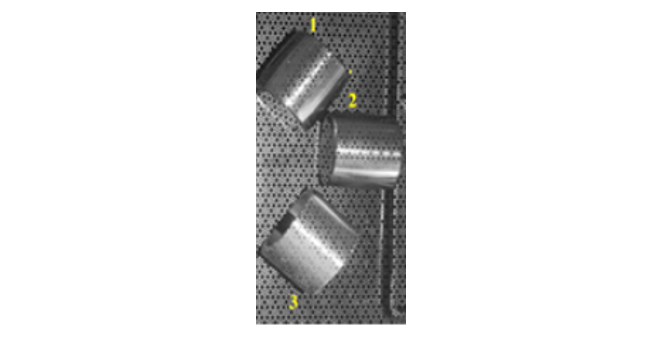
Fig. 5 – Shiny rollers used in roller bearings scanned by the grid scanner