bottlenecks in bin-picking
October 04th, 2019
Overview of bottlenecks in bin-picking
by Ivar Balslev, Senior developer, Scape Technologies
Content
Steps in the bin-picking and the orientation control
- Recognition and pose estimation of one or more parts in the bin
- Choice of robot and gripper
- Moving the gripper - without collisions - to the part and making a firm grip
- Change from an unprecise to a precise grip
Other challenges on the road to feasible solutions
- Is the cycle time short enough?
- How to handle mixed symmetries?
- How to develop generic software tools for run-in of new parts?
Introduction
A commonly encountered handling task in industry is to pick parts piled randomly in a bin and to place each picked part in a precise position somewhere in an automated work cell, i. e. a manufacturing machine, a fixture, an assembly system or the like. It is estimated that in the US, one third of the manufacturing labor force moves parts manually from bins and to structured positions in automated work cells.
The bin-picking itself is followed by a place process. The location and orientation of the part in the place position must be well defined and precise. The handling process between the actual bin-picking and the final placing is here called orientation control. SCAPE Bin-Picking Solutions normally include both bin-picking and orientation control.
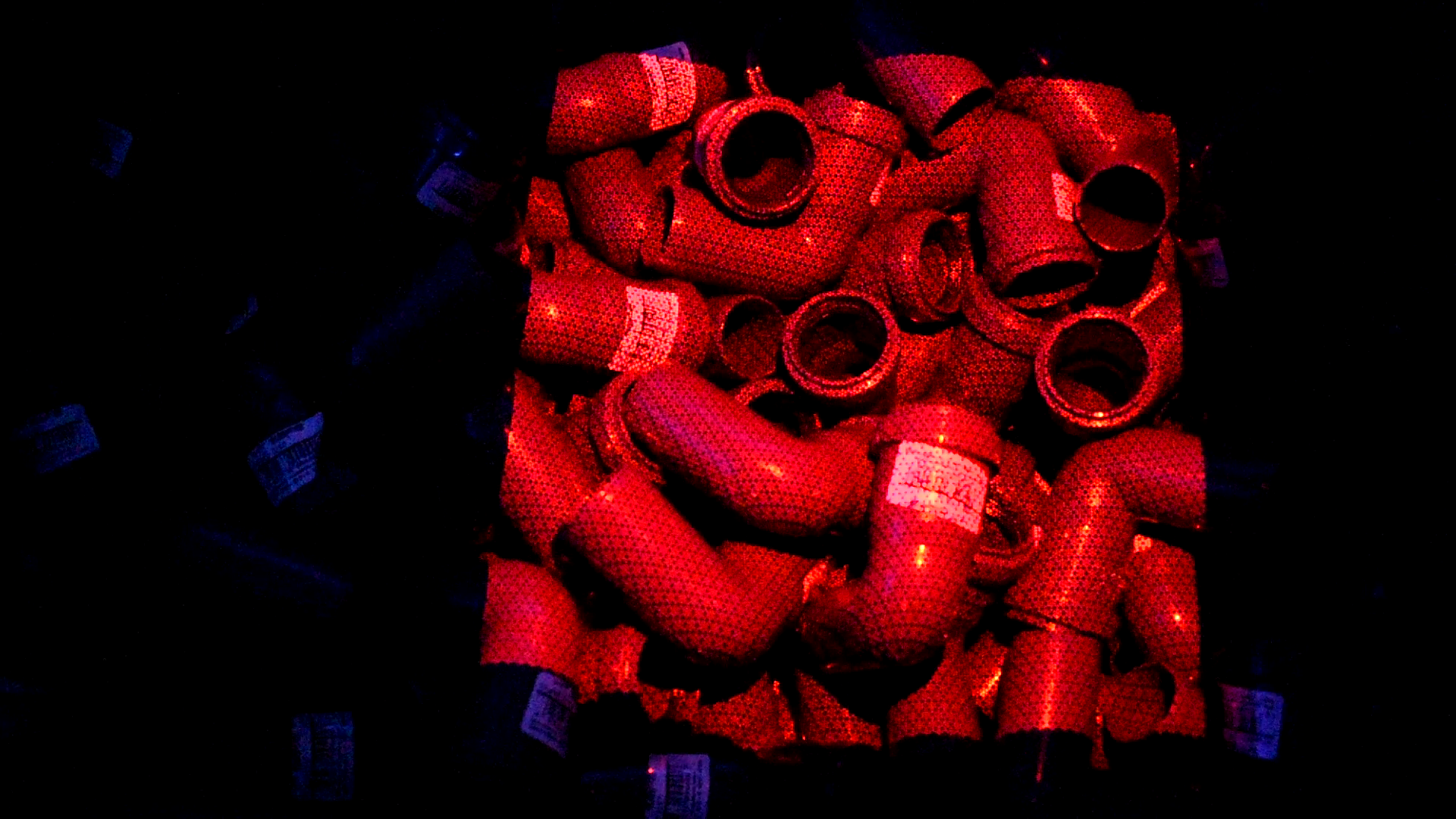
Fig. 1 - Cylindrical parts in a random pile
Bin-picking in industry has been automated very slowly during the last 30 years – compared with other handling processes such as welding, spray painting, stacking and assembly by blind robots, etc. In this article and the later articles to come, it will be clear to the reader why the automation of bin-picking has been slow. It will be understood that bin-picking is a very complex process with severe technical bottle necks, particularly if both the bin-picking and the subsequent orientation control is involved.
This first article is a birds’ eye view on the challenges of bin-picking and orientation control.
Steps in the bin-picking and orientation control
1. Recognition and pose estimation of one or more parts in the bin
The most effective way of recognizing the parts in a bin is 3D scanning. Scape Technologies uses two different types of scanners: a) a stationary scanner mounted above the bin or b) a robot mounted scanner. Any of these scanners have - as primary output - a point cloud, i.e. a list of 3D points corresponding to surface points in the scene.
Such a point cloud contains 30.000-900.000 points. In the recognition process, the point cloud and the shape of the part (defined by a CAD file) are fitted together, thereby determining the pose (position and orientation) of one or more parts. Bottlenecks here are: Are the sensors cheap enough? Is the spatial resolution sufficient?
Can the sensor stand an industrial environment? Can shiny parts be handled? Are the scanning and recognition algorithms fast enough?
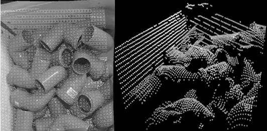
Fig. 2 – Scanner result from a tool mounted scanner. At left a 2D image of the scanning points in the scene. At right a perspective view of the resulting point cloud.
2. Choice of robot and gripper
In SCAPE cells the end effector is usually a so-called tool unit. Such a tool unit may have up to five grippers. The robot should be large enough to carry the tool unit, the gripper(s) and the part.
If the parts have large enough planar surface regions and are not too heavy, the preferable gripper is a suction cup. Slightly more effective is a magnet (unless the part is nonmagnetic). If suction cups or magnets are not sufficient, then one must use two-finger grippers. In order to optimize weight and gripping force two-finger grippers in SCAPE cells are pneumatically driven.
In case of more than one gripper on the tool unit, it is necessary to mount each gripper on a linear guide which is mounted on the tool unit. This allows the active gripper to be moved down, thereby avoiding unused grippers to collide with the bin content.
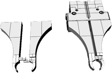
Fig. 3 – A typical two finger gripper for round objects. At left, the fingers are shown in open state. At right the pneumatic actuator is included. Note the structure for preventing grips of two objects at a time.
3. Moving the gripper - without collisions - to the part and making a firm grip
Scape Technologies has developed a grip manager. This software contains a part specific list of grips (i.e. part positions in the coordinate system of the gripper), see Fig. 4, right. When a part is recognized, it is determined which grips in this list can be realized without collisions between the robot end effector and other parts of the system (bin walls, bin bottom, neighbor parts etc.). This collision check demands full knowledge of 1) the geometry of the end effector during the planned robot motions, 2) bin walls and bottom, 3) neighbor parts, 4) other potential obstacles. Finally, one of the allowed grips is realized, and the gripper is activated.
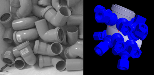
Fig. 4 – Left: Plastic angle tubes lying at random, right: specification of suitable suction cup grips.
4. Change from an unprecise to a precise grip, orientation control
This task can be very complex. The problem is that - initially - the part pose in the gripper is not always known with high enough precision, and so normally the part cannot be placed without a regrip. SCAPE cells use the following orientation control methods:
a) An intermediate self-aligning fixture: The most simple and fastest orientation control is an inclined box corner used in case of cylindrical objects. Here the part pose in the gripper frame is approximately known. The part is dropped from a low height above the box corner. It will (hopefully) land in a position with well-known pose from which it is regripped, see Fig. 5. Instead of a box corner one may use other forms of self-aligning intermediate fixtures.
b) Handling station: This is the most generic method of orientation control. The robot drops the part on a plane table above which is mounted a simple (2D) camera, see Fig.6. During run-in, so-called support modes, i.e. possible resting positions of parts lying on a planar table, have been defined for the part in a virtual environment. This information and the camera image define the part pose with high precision.
After orientation control a second, precise grip is realized. If this regrip happens to be upside-up the robot can place the part directly in the final place position. Otherwise the robot must place the part in a part turner, turning the part 90 or 180 degrees. Then the robot can perform a second regrip, suitable for the final place process. The part turner should have – to some extent – self-aligning fingers.
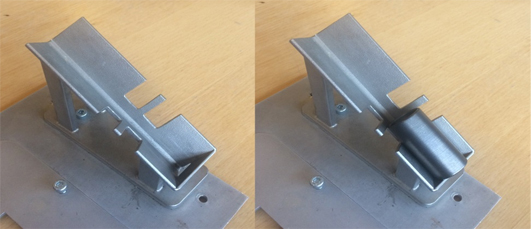
Fig. 5 – Box corner type intermediate fixture for round objects, shown without (left) and with (right) a part
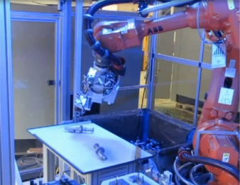
Fig. 6 – A handling station with two visually isolated objects. The bin is to the right of the handling station, and the robot has a finger gripper shown in Fig. 3. The camera above the handling station and the final place fixture are not shown.
Other challenges on the road to feasible solutions
There are many other bumps on the road to sufficiently effective and feasible bin-picking solutions. In this section we briefly describe the most important additional bottle necks.
1. Is the cycle time short enough?
The feasibility of a bin-picking installation often depends on the cycle time achieved. In minimizing the cycle time one must schedule the scanning and recognition so the robot never waits for the part pose estimation to finish. To achieve this Scape Technologies has developed the bin-picking system so all recognition calculations take place while the robot is moving.
The minimum cycle time thereby depends only on how fast the robot can move. In some portions of the robot cycle, the risk of dropping the part may give severe acceleration limitations.
Frequently, the end users require so short cycle times, that more than on robot must be active. An often installed configuration in this case includes a bin picking robot and a line feeder robot. The line feeder robot performs the precision grip at the handling station, and places the part in the final place position.
2. How to handle mixed symmetries?
The part in Fig. 7 has six-fold rotation symmetry, if the logo at right is not detected. If the 6 holes are not clearly detected, the part has full rotation symmetry. If the logo is resolved, the part has no symmetry. In other words, the part symmetry depends on the recognition precision. The primary recognition is often insufficient for revealing details like the logo in Fig. 7.
If the end user wants precise position of the logo in the final place position then one must add a second recognition step concentrated on the logo. Scape Technologies has developed such a second recognition step, based on artificial intelligence.
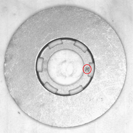
Fig.7 – A part with mixed symmetry. The logo is inside the red ellipse.
3. How to develop generic software tools for run-in of new parts?
The most challenging aspect of bin-picking is the limitation of engineer hours spent on run-in of bin-picking solutions handling new parts. Introducing new part shapes and sizes requires a lot of work:
1) Previously developed two-finger grippers needs to be modified
2) The list of grips (see Fig. 4, right) must be redefined
3) Fine tuning of the scanning and recognition settings needs to be performed again
4) Teaching of the robot’s placing at final place needs to be performed again
5) Minimization of cycle time needs to be performed again
6) Handling of mixed symmetries needs to be trained
In order to make these steps easy, Scape Technologies has developed tools and tutorials, so that partners can perform these run-in steps with little or no assistance.